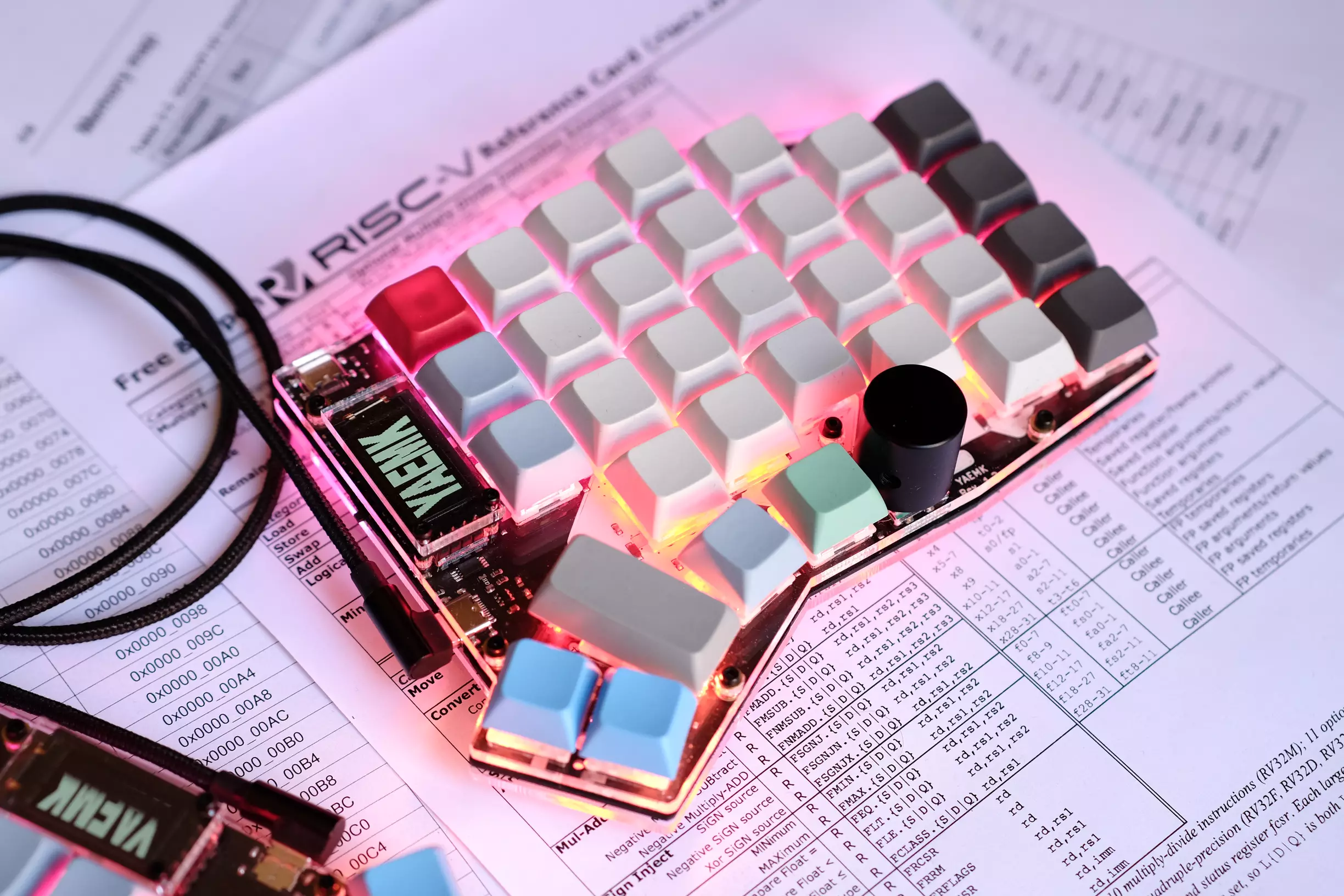
Features of the YAEMK
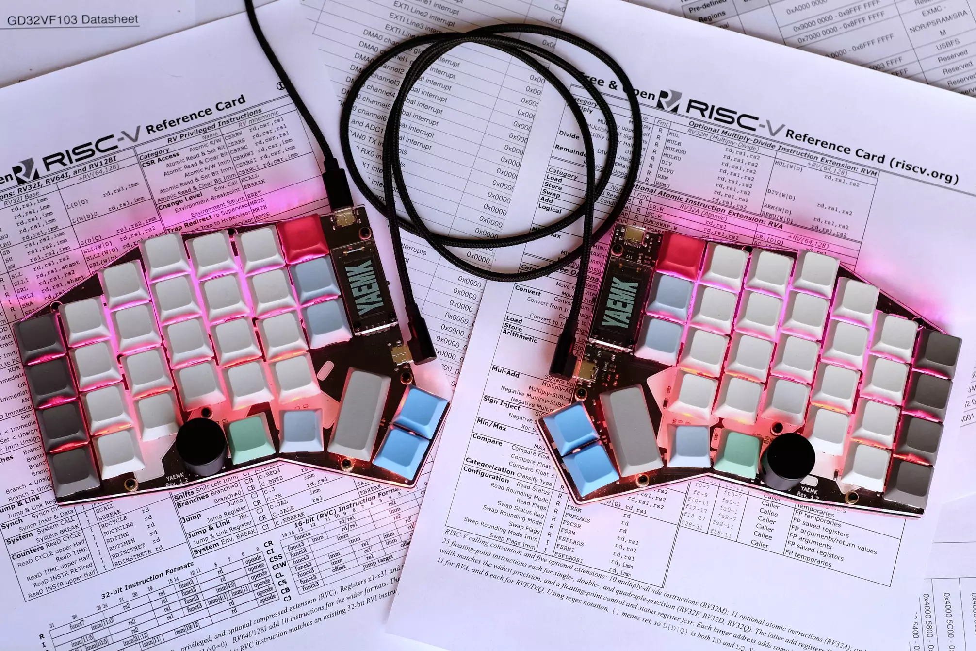
- Split-Keyboard with 5 rows by 8 columns matrix with columnar stagger. Key layout testers for print (A4 and Letter) available!
- All 64 to 66 Keys are MX-compatible and hot-swapable.
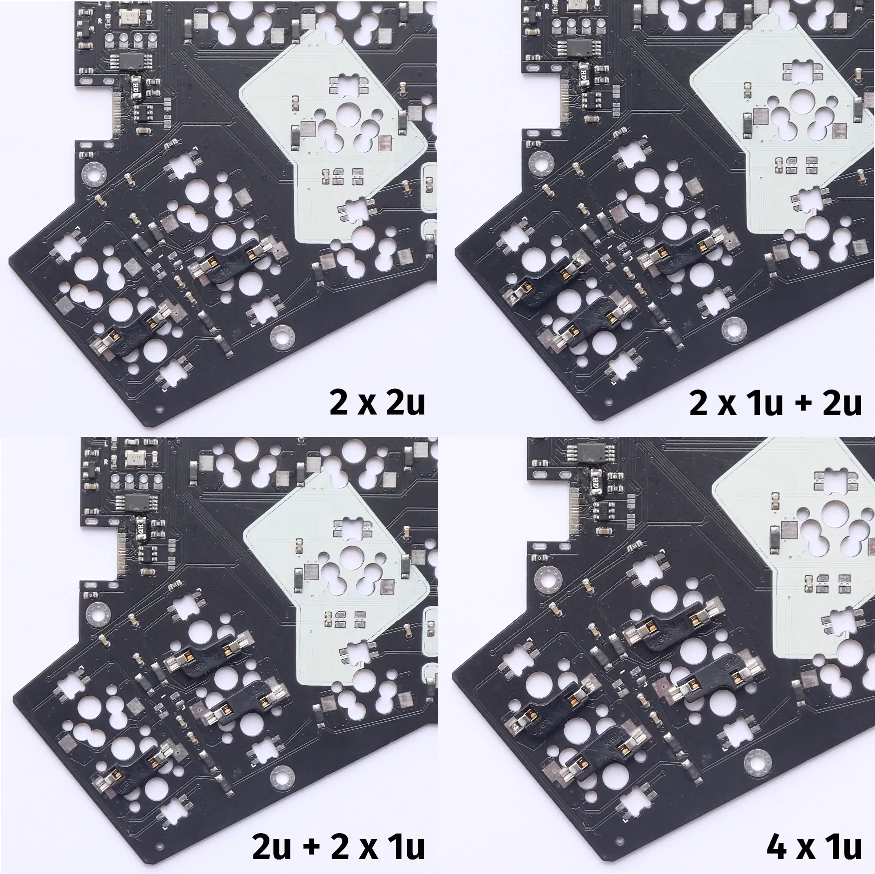
- The thumb-cluster is configurable in 4 different configurations,
just solder the hot-swap sockets to your needs.
- 4x1u, 2x2u, 2u+2x1u or 2x1u+2u configuration possible.
- Inspired by the marvelous Kyria from Thomas Baart!
- On-board ARM microcontroller (STM32F303CCT6) or RISC-V microcontroller (GD32VF103CBT6)
- Worlds first RISC-V (Split-)Keyboard!
- Fully supported by QMK Firmware
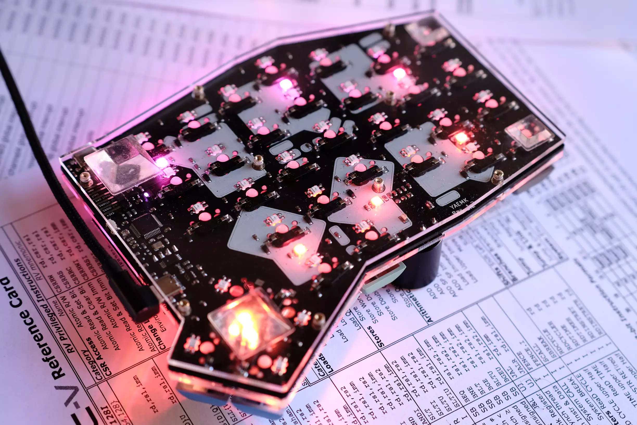
- Per-Key RGB back lighting with 66 easy to solder SK6812-mini-e LEDs
- Underglow RGB with 14 SMD SK6812-mini LEDs
- USB-C Hot-plugable sockets for USB connection, and split communication between the halves
- Two 0.96” OLED displays for comprehensive information (I2C SH1107 64x128 Pixel)
- 2 x Rotary encoders for scrolling, volume changes etc.
- On-board 64KB I2C EEPROM for settings, keymaps etc.
- Open-Source, single PCB design for both sides.
- PCB SMT assembly files for JLCPCB in the repo!
- 2-plate acrylic case files available.
Table of contents
- Features of the YAEMK
- Build Guide
- 1 The Boards
- Ordering process
- Additional bill of materials for one complete Keyboard
- Placement of hotswap sockets for thumbcluster
- Correct orientation of hotswap sockets
- Correct orientation of rgb leds
- Modification of SH1107 display modules
- Step-by-step Instructions
- Finished left handed PCB for reference, switches are already installed
- Troubleshooting
- 2 Acrylic plate case
- 3 Magnetic tenting legs
- 4 Firmware
- 1 The Boards
YAEMK Key layout testers

Find out if building a YAEMK fits your hands, available in:
Thumbcluster configurations
Four thumbcluster configurations are possible, depending on the location of the soldered hot swap sockets. Every configuration has a dedicated top plate for the case in the repository.

Build Guide
DISCLAIMER: At the time of writing (11th of May 2021),
there is a world wide, on-going semiconductor shortage.
Both MCUs of the YAEMK,
the STM32F303CCT6 and
GD32VF103CBT6
are affected by this shortage
and are out of stock.
The GD32VF103CBT6 can be sourced from devboards like the Sipeed Longan Nano,
but desoldering requires a hot air station.
Also the GD32VF103 requires installing a GCC RISC-V toolchain,
a recent dfu-util with fixes for the DFU bootloader.
The complete design including schematics, gerbers, pcb smt assembly files and a acrylic plate case are open source and available in the repository. The complete project can be opened with the open source KiCad EDA.
If you have never soldered before, the YAEMK will be quite a challenge. Therefore it is recommended to buy yourself some SMD soldering practice kits and learn it beforehand.
1 The Boards
Building your own YAEMK involves ordering the PCBs from JLCPCB with PCB SMT assembly, so nearly all components come pre-soldered. Only through hole components, tactile-switches, connectors and SMD components have to be soldered by you. It is crucial to understand that the YAEMK pcb is flip able, which means that every circuit board can be turned once into the left or right side of your keyboard. Depending on right or left handedness of the PCB these components have to be soldered either on the front or back side of the pcb. The whole process is documented in detail below. The tools you will need are a good quality pair of tweezers, flux, leaded solder and a temperature controlled soldering iron, a hot air station is recommended but not strictly necessary. For easy component location and sourcing of parts, it is recommended to use the interactiv HTML BOM.
Ordering process
If you have never ordered PCBs with assembly from JLCPCB, I highly recommend watching the steps from Phil’s Lab in the KiCad STM32 + USB + Buck Converter PCB Design and JLCPCB Assembly video. The default settings are mostly fine; The changes you want to pick are the following:
PCB
- Use the gerbers.zip file from the PCB folder for upload.
- The Gerber preview has timeouts from time to time when uploading to JLCPCB.
Just fill a width of
166mmand a height of131mm. - 2 Layers (The video has a 4 Layer board)
- PCB Oty: As much as you like
- PCB Color: Black
- No impedance control (Option only shown in the video)
- Surface Finish: HASL(with lead) if you want the easiest soldering experience, or LeadFree HASL. For extra bling-bling choose ENIG gold finish.
- Remove Order Number: Yes
SMT Assembly
ATTENTION: At the time of writing (11th of May 2021), there is a world wide on-going semiconductor shortage, both MCUs of the YAEMK the STM32F303CCT6 and GD32VF103CBT6 are affected of this shortage and are out of stock. Therefore you currently can not order the pcb with the MCU pre-soldered. I was not able to correct and confirm the MCU orientation, it is likely rotated in correctly. As soon as the MCU is in stock again this will be addressed.
- Assemble top side
- SMT Oty: As much as you like
- Tooling holes: Added by Customer
- Add BOM file:
the file is PCB/assembly/YAEMK_bom.csv
- If the default EEPROM and Opamp are out of stock, you can try the alternate BOM file: the file is PCB/assembly/YAEMK_bom_alternate_eeprom_and_opamp.csv
- Add CPL file: the file is PCB/assembly/YAEMK-top-pos_corrected.csv
- If you want the GD32VF103 MCU,
deselect
U5 STM32F303CCTxon the Select Parts page. You have to source and solder the GD32VF103 yourself.
After placing your order you can proceed ordering the missing parts from LCSC, as they are both part of the same company, you can save shipping costs when specifying your JLCPCB order number.
Additional bill of materials for one complete Keyboard
All components that are NOT pre-soldered by JLCPCB are listed in this table and have to be bought and assembled by you. Switches and Keycaps are highly personal decision, you find my recommendation at the bottom. As I’m using a rather uncommon keyboard layout (K.O,Y) I stick to blank keycaps.
Personal recommendation of Aliexpress stores:
| Amount | Part | LCSC | Link | |
|---|---|---|---|---|
| 4 | USB-C Socket Mid-mount | C168688 | LCSC or Aliexpress | |
| 2 | Alps EC11 Rotary Encoder | C370986 | LCSC | |
| 5 | LMV321 Opamp (Backup) | C686637 | LCSC | |
| 66 | SK6812-mini-e (3228) RGB LEDs | - | Aliexpress | |
| 14 | SK6812-mini (3535) RGB LEDs | - | Aliexpress | |
| 66 | Hotswap Kailh or Gateron Sockets | - | Aliexpress | |
| 2 | Encoder Knob | - | Splitkb or Aliexpress or Aliexpress | |
| 2 | 0.96” SSD1107 64x128 Display | — | Aliexpress | |
| 2 | Blue 0603 Power LED | C72041 | LCSC | |
| 2 | Reset/DFU Switch | C393942 | LCSC | |
| 2 | Display Socket | C358718 | LCSC | |
| 2 | Debug Pinheader (optional) | C56816 | LCSC | |
| 66 | Switches (depending on Thumbcluster) | - | Personal recommendations Clicky - Box Yellow or Tactile - Boba U4 RGB or Linear - Boba Bobbagum | |
| 64-66 | 1u Keycaps (depending on Thumbcluster) | - | e.g. 1u XDA Profile caps Aliexpress | |
| 0-4 | 2u Keycaps (depending on Thumbcluster) | - | e.g. 2u XDA Profile caps Aliexpress |
Tip: Buy some excess LEDs as they are heat sensitive!
Placement of hotswap sockets for thumbcluster
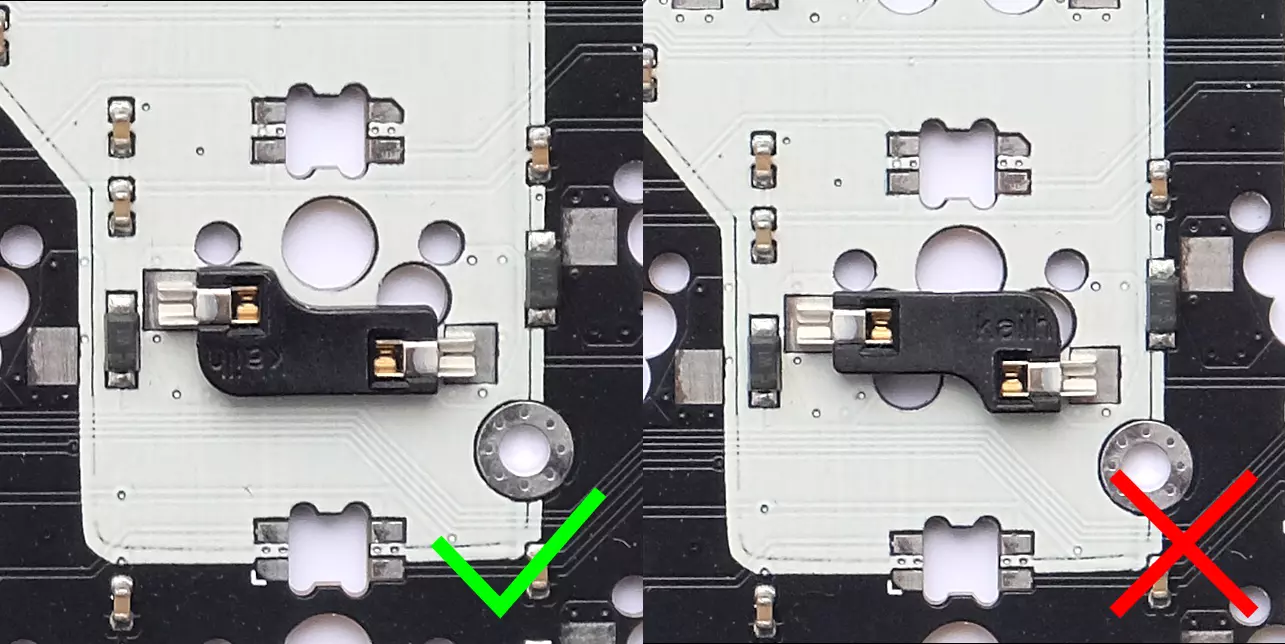
Correct orientation of hotswap sockets
Do not obstruct the middle hole with the hotswap sockets or switches will not fit!
Correct orientation of rgb leds
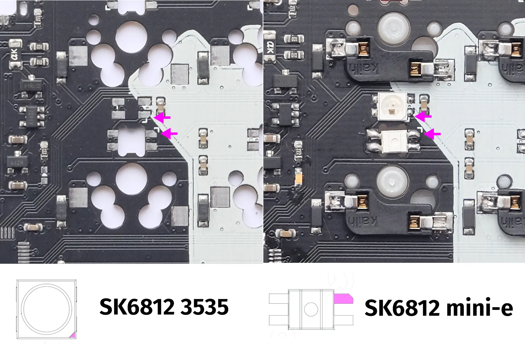
Every led has little chamfer that indicates the correct orientation, match it with the chamfer on the pad of the PCB and the little white triangle silk screened next to the pad. Two types of leds are used on the YAEMK the first sk6812 3535 are for underglow, there are 7 per side in total and distributed along the edges of the PCB, it is the upper led in the picture. They shine down on the surface the keyboard rests on. The second type are sk6812-mini-e leds for per-key backlighting, it is the lower led in the picture. They shine up through the PCB, away from the surface the keyboard rests on.
Modification of SH1107 display modules
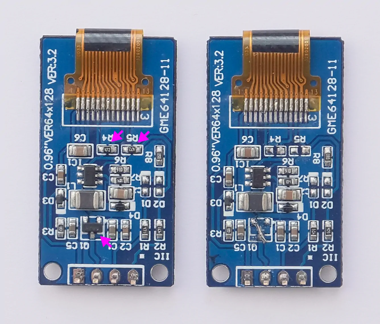
Remove the pull-up resistors R4 and R5 with your soldering iron,
these redundant as the YAEMK already has pull-ups in place.
Remove the low drop out (LDO) regulator Q1
by cutting its legs or with your soldering iron
and bridge the terminal by soldering a small piece of wire in place.
The LDO is redundant and serves no function,
as the YAEMK already supplies the display with stabilized 3.3V VDD.
Step-by-step Instructions
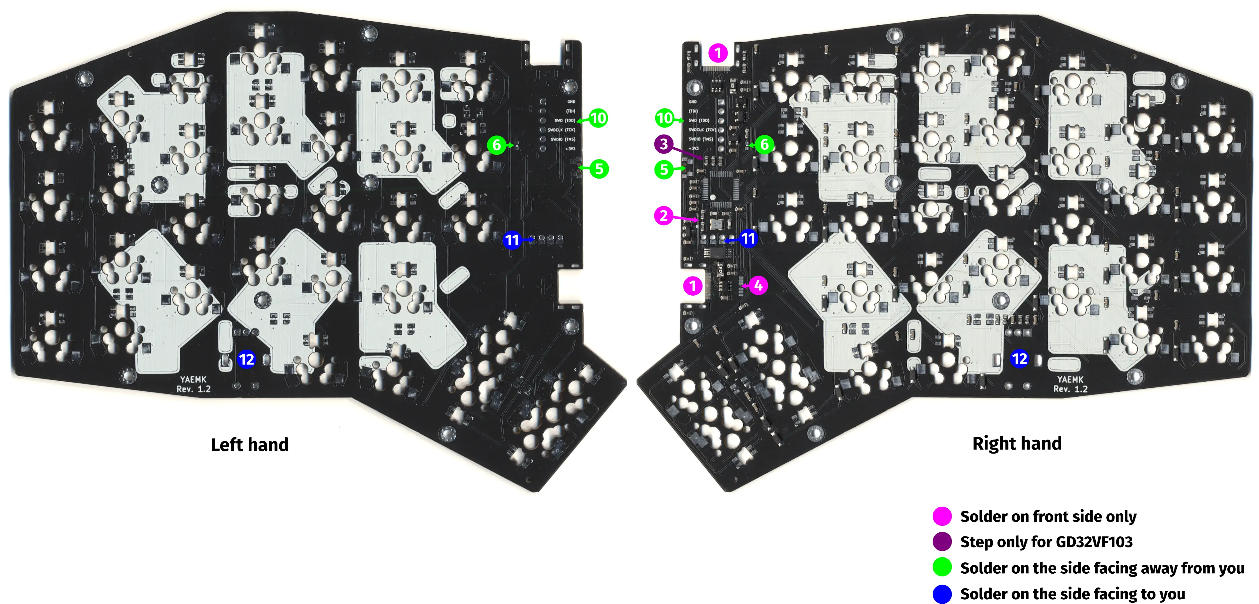
Note: the picture shows pcbs without an mcu.
Emphasized text like
P1 and P2are the component references, you can find them in the schematic and interactive bom.
- Solder USB-C Sockets for USB connection and Split communications.
P1 and P2- Make sure to apply enough solder and thoroughly wet the pins that secure the socket with the PCB.
- Remove handedness selection resistor
R24 or R25- The handedness, meaning if it is the right or left side of the keyboard,
is determined by these resistors.
PCBs come with both resistors soldered in place from JLCPCB.
Keep the resistor for the side you want this PCB to be,
e.g. keep resistor
R25next to the little R if this PCB should be the right side of the keyboard and remove resistorR24next to the little L.
- The handedness, meaning if it is the right or left side of the keyboard,
is determined by these resistors.
PCBs come with both resistors soldered in place from JLCPCB.
Keep the resistor for the side you want this PCB to be,
e.g. keep resistor
- (GD32VF103 only) Remove USB D+ pullup resistor
R20 - Close split communication solder jumpers
JP1 and JP2- Both halves of the YAEMK communicate via a full-duplex USART connection over a USB-C cable (we re-purpose the USB cable for this). For this to work the TX lines of one halve have to be connected with the RX line of the other halve. That’s what the solder bridge is for, to reroute the TX line of one halve into the RX line of the other.
- Connect the bottom pad with the middle pad on both jumpers via a solder bridge on the left side of the keyboard.
- Connect the top pad with the middle pad on both jumpers via a solder bridge on the right side of the keyboard.
- Solder Reset/DFU Switch on the side facing away from you.
S32 - Solder power LED on the side facing away from you.
D70- A little triangle shows the orientation of the LED on the board, match this triangle with the triangle on the bottom of the led.
- Flash the testing firmware provided and test for successful usb connection.
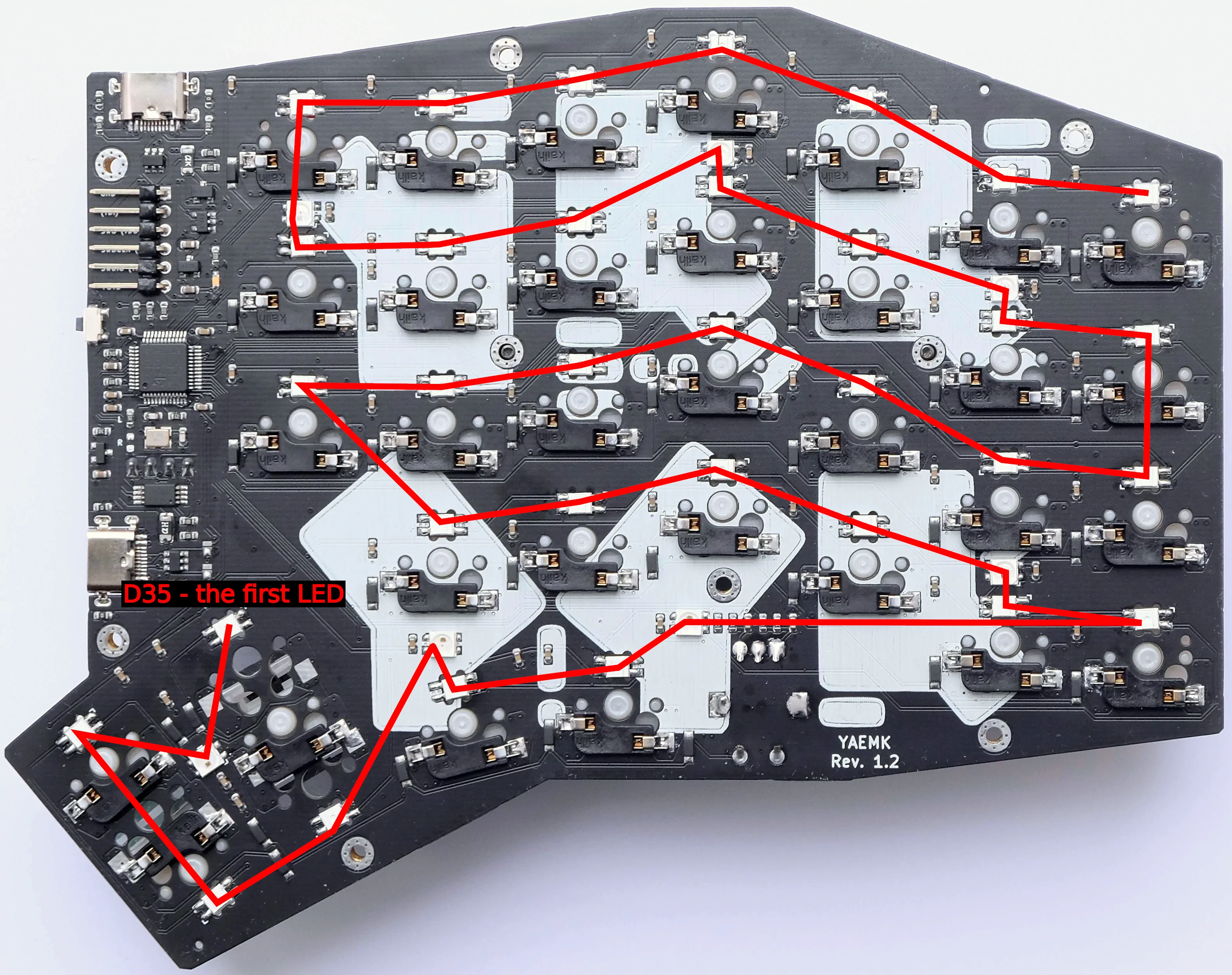
- Solder RGB LEDs on the side facing away from you.
Make sure to correctly orient them,
as they are not the same orientation all the time.
Use the interactive BOM when in doubt.
D35 to D76. Check that all LEDs are working by connecting the board to USB (the firmware from step 7 turns on all the LEDs). Note that as LEDs are connected in chain - one dead LED leads to all subsequent leds being off. - Solder MX Hotswap Sockets on the side facing away from you.
Decide for a thumbcluster configuration.
Make sure to correctly orient them.
S1 to S31 - (Optional) Solder Debug Header on the side facing away from you.
J1 - Solder Display Socket on the side facing to you.
P3- Bridge the pads next to the through holes when soldering to close the contact.
- Solder Rotary Encoder on the side facing to you.
SW1 - Clean the Board from any residues with alcohol.
- Modifiy the SH1107 displays by removing the pull-ups and the LDO as demonstrated.
- Trim the plastic and the pin header of the display so that the pcb of the display sits flush on the display socket.
- (Optional) Paint the edges of the pcb with a black marker pen.
- (Optional) Paint the blue display frame and pcb edges with a black marker pen.
- Test board for full operation, see Troubleshooting notes below in case of errors:
- Displays show YAEMK logo on startup on both halves.
- Successful USB connection of both halves to the pc, regardless of plug orientation. Make sure that the default Layer designator “QWERTY” on the OLED is surrounded by two small dots. This indicates that this side has a USB connection.
- Successful split connection between both halves, regardless of plug orientation. If both sides claim to have a USB connection (“QWERTY” on the OLED is surrounded by two small dots on both sides) altough one is clearly powered by the other and has no direct USB connection to the PC (the peripheral half) jump to Peripheral half show USB connection.
- Key presses for all keys are registered, for testing bridge the terminals of the hotswap-sockets with a piece of wire.
- All leds fully light up, no flickering when slightly bending the pcb.
- Rotary encoders register motion.
- Reset+DFU tactile switch resets the board on short press and enters DFU bootloader on long press (see GD32VF103 specific notes in Firmware section).
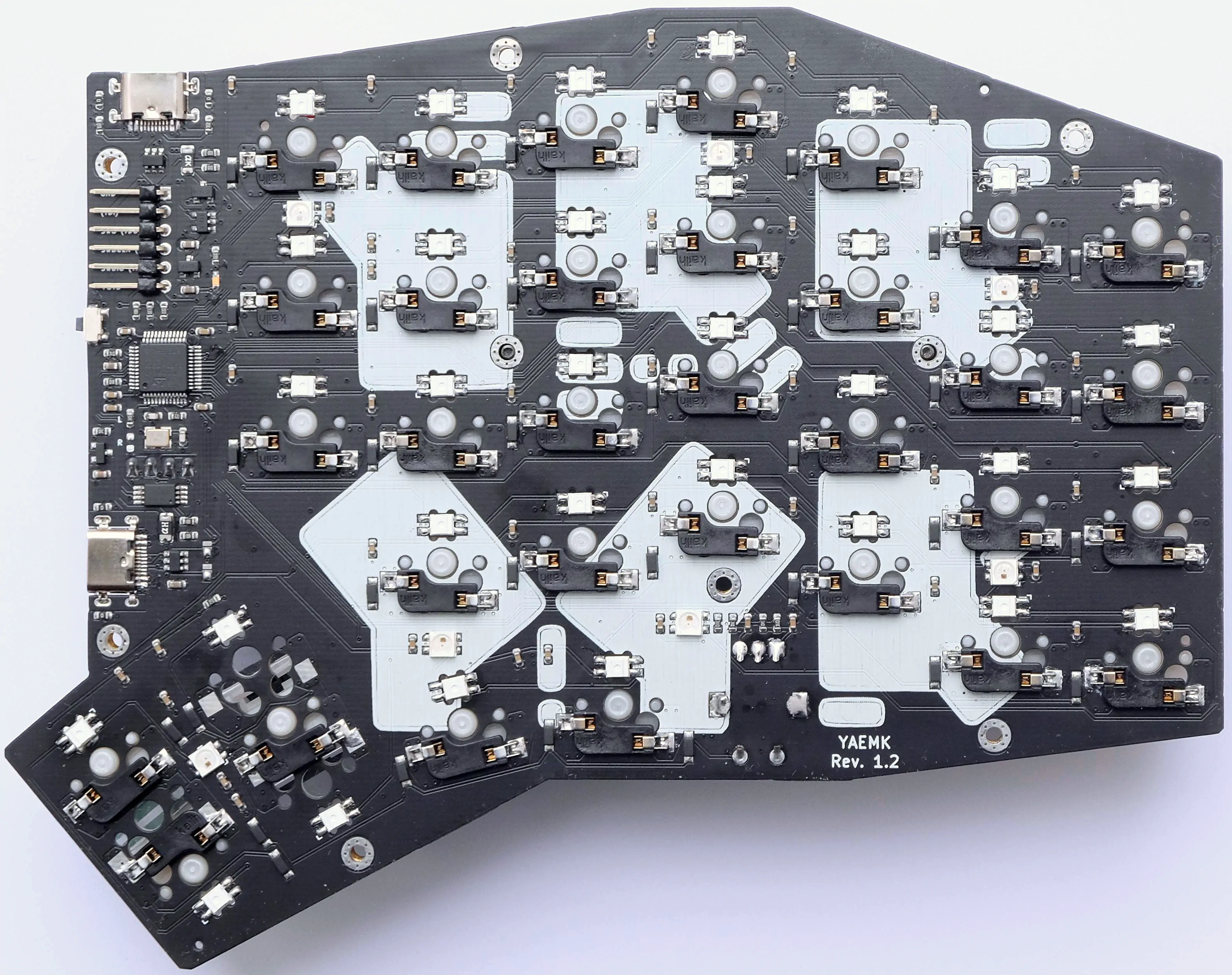
Finished left handed PCB for reference, switches are already installed
Troubleshooting
General debugging and logs
QMK offers debug logs via USB connection, so if your YAEMK already connects successfully over USB you can use these. Follow the official QMK guide and apply these changes to the firmware.
In rules.mk
change these options:
CONSOLE_ENABLE = yes
and in yaemk.c
void keyboard_post_init_user(void) {
    // Customise these values to desired behaviour
    debug_enable   = true;
    debug_matrix   = true;
    debug_keyboard = true;
    debug_mouse    = true;
}
Peripheral half shows USB connection
In rare cases,
the USB connection detection malfunctions,
and the peripheral half it is connected to and powered by the primary half,
claims that it has a USB connection as well.
This is the case if “QWERTY” on the OLED
is surrounded by two small dots on both sides.
In this case the split connection does not work
and the primary half feels sluggish.
The root cause is often a malfunctioning LMV321 Opamp with designator U6.
The highly recommended fix is to replace it with a new one.
A temporary workaround is disabeling the USB detection in software
by commenting out the is_keyboard_master()
in yaemk.c
and afterwards recompiling and flashing the firmware.
Sluggish keypresses / Keys not registered
Make sure to have OLED screens and the EEPROM in place
when you use the default firmware,
otherwise heavy timeouts will lead to missed keypresses.
If you don’t want to use OLED screens and/or EEPROM,
change these defines in rules.mk
and recompile the firmware.
EEPROM_DRIVER      = transient
OLED_DRIVER_ENABLE = no
No USB connection
Make sure that you soldered the pins of the USB-C sockets to the pads,
if in doubt reflow with solder and flux.
Test for continuity with a multimeter on the d+ and d- lines
between the legs of the ESD protection diode U3
and a plugged in USB-C cable.
No split communication
Make sure that you soldered the pins of the USB-C sockets to the pads,
if in doubt reflow with solder and flux.
Test for continuity with a multimeter on the TX and RX lines
between the legs of the ESD protection diode U4 on both halves,
connecting them with a USB-C cable.
Make sure that you closed the solder bridges
in opposite fashion on both halves,
i.e. the left halve bridged the left pads with solder bridges
and the right halve bridged the right pads with solder bridges.
No power
Check for shorts between VDD and GND with a multimeter. Make sure that the USB-C sockets are soldered the their pads, if in doubt reflow with solder and flux.
LED chain broken or flickering LEDs
Check the correct orientation of the rgb led first, correct if necessary. If correct, try to apply some pressure to the first LED that doesn’t work in the chain, if this turns on the LED you have cold solder connection - reflow the LED. Should that not work, try the last LED in the chain that does work properly, if that turns on other LEDs in the chain, the problem was the again a cold solder connection - reflow the LED. If all that doesn’t help try to re-solder these leds, even if applying pressure didn’t help. If that doesn’t solve the problem one of the leds is dead, replace with a new one.
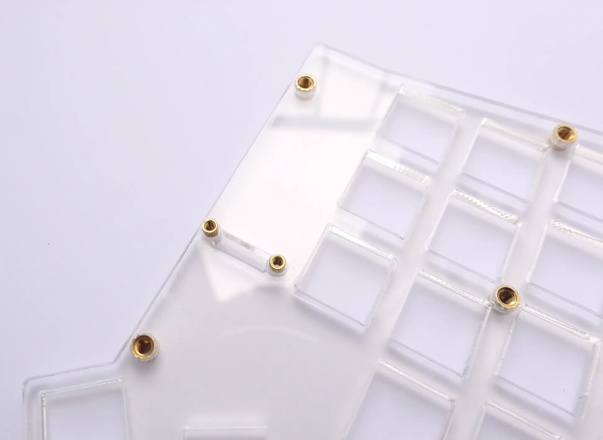
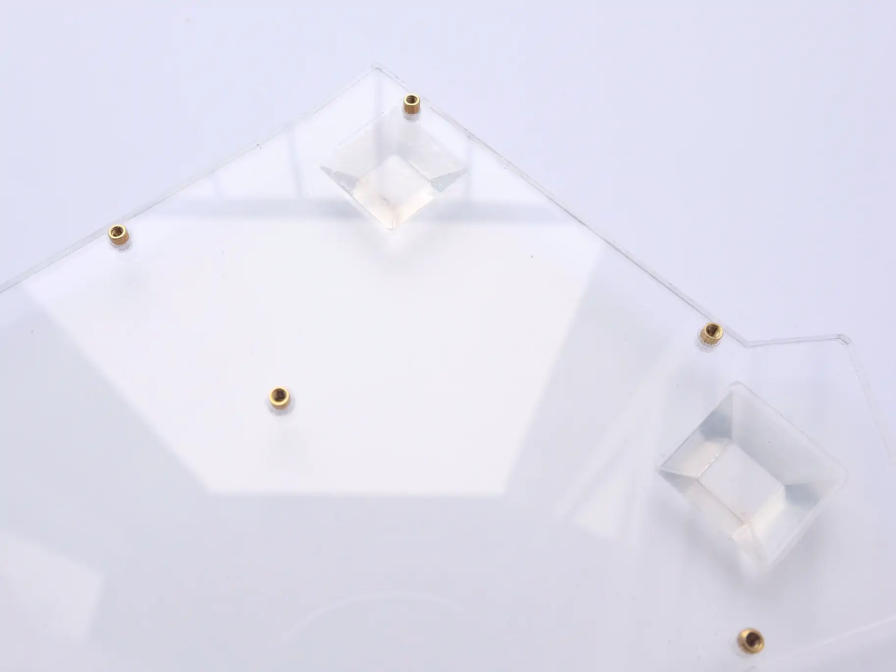
2 Acrylic plate case
The official YAEMK case consists of one top and bottom plate and a display cover for each side and is made out of 3mm acrylic plates. All designs are flipable, so each plate can be used for the left or right side of the keyboard. For each thumbcluster configuration a specific top plate was designed, the bottom plate is universal for all configurations. You can find the SVG files in the repo once without kerf and once with a kerf of 0.1mm for laser cutting. Cast Acrylic is highly recommended for its clearer appearance and sturdiness, extruded acrylic is brittle and prone to cracks!
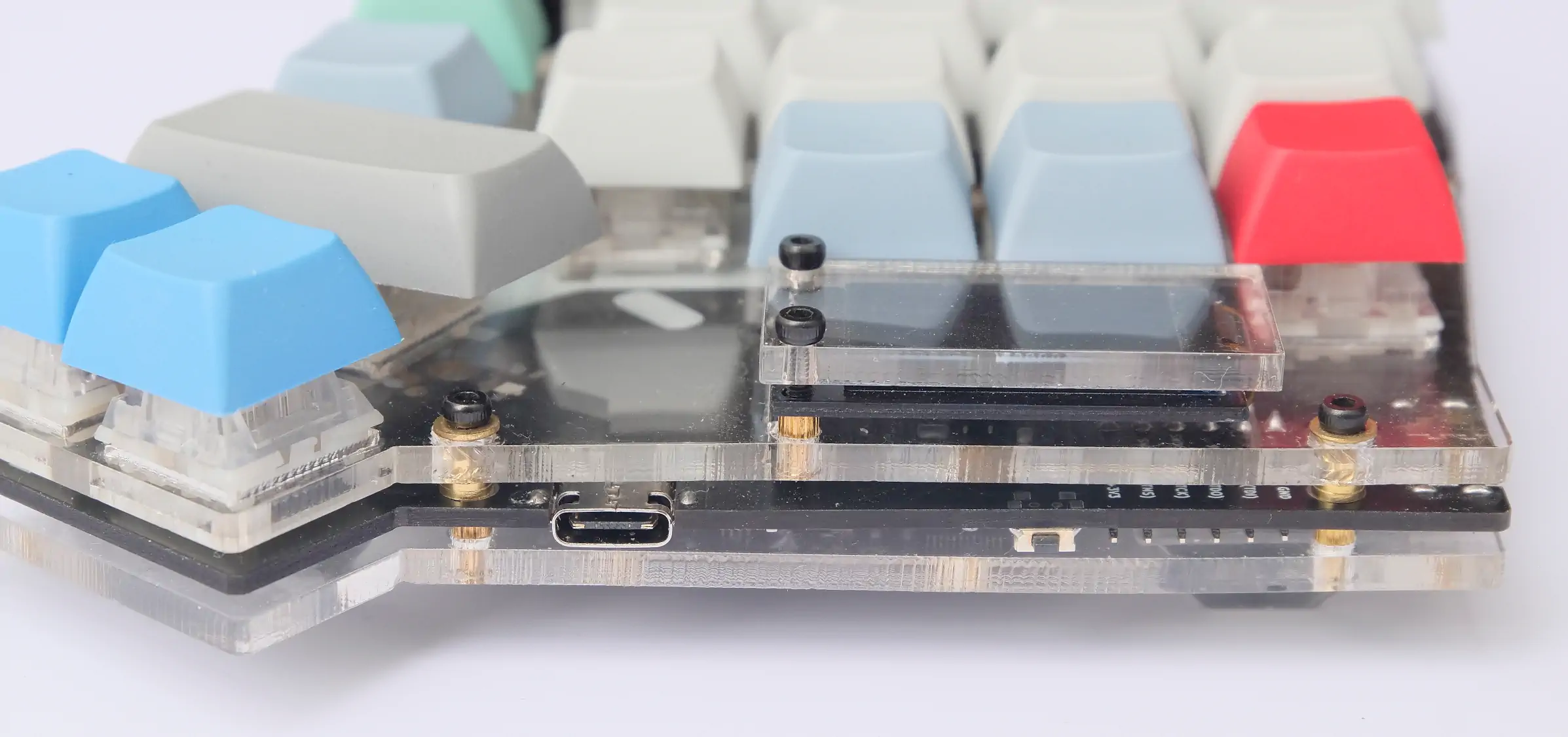
Case principle

The pcb is clamped by the brass M3 insert and M2 standoff by tightening the M2 screw which only has grip in the M2 standoff. The Display is clamped between the cover and the M2 standoffs of the top case and display socket. Both brass inserts are melted flat to the surface into the acrylic plates using a soldering iron set to 160c and a pointed tip, like the T12-I. Watch this video to get a understanding of the process.
Bill of material for one case
| Amount | Part |
|---|---|
| 2 | YAEMK Top plate |
| 2 | YAEMK Bottom plate |
| 2 | YAEMK Display cover |
| 8 | Transparent rubber buffers |
| 22 | M2x12mm Screws |
| 22 | M2x5x3.2mm Round brass standoffs |
| 18 | M2x5mm Round brass washers |
| 18 | M3x5x4.6mm Round brass insert nuts |
All size designations for the standoffs and insert nuts are
(dxHxD).d= inner diameter,H= height andD= outer diameter.
Step-by-step instructions

Pay attention to make all inserts flush with the surface! If acrylic obstructs the inserts after insertion remove it while it is still warm.
- Melt M3 insert into the top plate.
- Melt M2 standoffs for the display cover into the top plate.
- Melt M2 standoffs into bottom plate.
- Assemble case with display and display cover.
- Insert switches and keycaps.
3 Magnetic tenting legs
Tenting can be easily added to the acrylic case by using the magnetic tenting legs originally invented by Manna Harbour.
Bill of material to add tenting to one case
| Amount | Part | Link |
|---|---|---|
| 4 | 20mm x 3mm disc magnets | Aliexpress |
| 4 | 20mm x 3mm countersunk ring magnets | Aliexpress |
| 4 | 10mm M3 flat head screws | — |
| 4 | 20mm or 25mm M3 standoffs | — |
| 4 | M3 Thumb screws | — |
| 8 | 6mm/8mm Round transparent rubber buffers | Aliexpress |
Step-by-step instructions
If in doubt follow the link to the article by Manna Harbour to get a clear idea of the tenting mechanism.
- Glue the disc magnets to the bottom of the case, be careful to have them in parrallel to each other. I used transparent double sided adhesive tape for this.
- Fix the countersunk ring magnets to the standoffs using the flat head screws.
- Fix the thumb screws to the standoffs.
- Add rubber buffers to the outer edges of the case and the thumb screws.
- Attach the legs to the case.
4 Firmware
YAEMK uses the Quantum Mechanical Keyboard Firmware (qmk). Until there is mainline support for YAEMK in QMK, you will have to use my QMK fork.
To flash it onto your board, follow these instructions:
- Make that you have cloned the yaemk repository,
including its submodules with git,
and not downloaded a release zip.
git clone --recurse-submodules https://github.com/KarlK90/yaemk-split-kb.git
- Install the
qmktool. You can find detailed instructions in the QMK getting started guide. - Put your board into the USB-DFU bootloader mode.
- STM32F303: Hold the Reset+DFU button, until your board registers as STM32 DFU bootloader
- GD32VF103: Hold the Reset+DFU button with the USB cable plugged in, detach cable and re-plug. Immediately release the button shortly after.
- Adjust features to your liking.
- Flash the firmware.
- For the ARM version:
qmk flash -kb karlk90/yaemk/arm -km default - For the RISC-V version:
qmk flash -kb karlk90/yaemk/riscv -km default
- For the ARM version:
GD32VF103 RISC-V GCC Toolchain and dfu-util
Debian 11 based distributions
A fully working RISC-V GCC toolchain is shipped beginning with Debian 11
and distributions based on it,
like Ubuntu 21.04.
It can be installed with the help of apt or apt-get:
sudo apt install picolibc-riscv64-unknown-elf binutils-riscv64-unknown-elf gcc-riscv64-unknown-elf- Tryout if
riscv64-unknown-elf-gccis found by runningriscv64-unknown-elf-gcc --versionfrom a terminal/command line/console. If successful, you’re done.
You should see an output similar to this:
❯ riscv64-unknown-elf-gcc --version
riscv64-unknown-elf-gcc () 10.2.0
Copyright (C) 2020 Free Software Foundation, Inc.
This is free software; see the source for copying conditions.  There is NO
warranty; not even for MERCHANTABILITY or FITNESS FOR A PARTICULAR PURPOSE.
Manual Installation
At the moment, the default QMK installation process doesn’t include a RISC-V GCC toolchain. Fortunatlly, there are pre-built toolchains available for a all major operating systems by EMBECOSM that we can install.
- Download the stable GCC toolchain from EMBECOSM for your operating system.
- Unpack the toolchain archive and copy to a folder accessible to your user.
- On Linux I used
/opt/riscv32-embecosm-ubuntu2004-gcc11.1.0(moved with root privileges).
- On Linux I used
- Add the bin folder
/opt/riscv32-embecosm-ubuntu2004-gcc11.1.0/binto your PATH environment Variable.- You might need to logout and login again, afterwards.
- Tryout if
riscv32-unknown-elf-gccis found by runningriscv32-unknown-elf-gcc --versionfrom a terminal/command line/console. If successful, you’re done.
You should see an output similar to this:
❯ riscv32-unknown-elf-gcc --version
Copyright (C) 2021 Free Software Foundation, Inc.
This is free software; see the source for copying conditions.  There is NO
warranty; not even for MERCHANTABILITY or FITNESS FOR A PARTICULAR PURPOSE.
For flashing,
dfu-util with a version of 0.10+ is needed,
because the DFU bootloader of the GD32VF103 has a bug in it.
- [Linux] Most Linux distributions pack version 0.9 of
dfu-util, if this is the case, you have to build it yourself following these instructions.-
To use dfu-util without root privileges, copy the udev rules
60-dfuse.rulesfrom thedocfolder to your udevrules.dfolder. Trigger a reload of the rules to apply them immediatly. *sudo cp doc/60-dfuse.rules /etc/udev/rules.d/ \ && sudo udevadm control --reload-rules \ && sudo udevadm trigger
-
- [Windows and MacOS] pre-built versions of dfu-util 0.10 are available. Download, unpack and add to path like the GCC toolchain.